Surface Morphology of Electrospun Fibers
Investigation of Phase Morphology for E-spun Fibers Composed of Polybutadiene and Polycarbonates

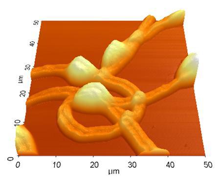
Figure 1. Topography information in Non-Contact AFM taken by XE-150 (50 μm scan size)
Electrospinning techniques are capable of producing polymer fibers in the nanometer scale. Polymer blends offer the potential to prepare new materials for use in a variety of applications. The focus of this investigation has been primarily on the phase morphology of the fiber surface.
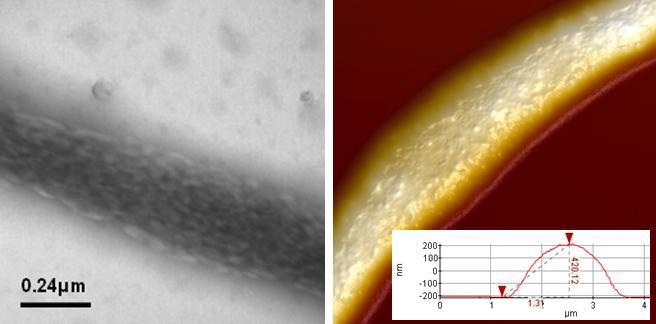
A large-scan (50 μm × 50 μm) view of an e-spun fiber is shown in Figure 1. There were a few bead formations along the length of the fiber. Figure 2 (a) shows the TEM images of polybutadiene (PB) / polycarbonate (PC) blends with weight ratios of 75/:25 after staining. The dark regions in the TEM images are identified as the PB phase and the light regions show the PC phase.
An electro-spun fiber was scanned in Non-Contact AFM and the resulting image is shown in Figure 2 (b). The features on the fiber surface were examined using the high performance Park AFM.

Figure 2. (a) TEM image and (b) AFM topography (6x6μm) and profile for e-spun fiber. Courtesy of Dr. Jun Seok Lee, Bongwoo Kang, and Prof. Changmo Sung, Univ. of Mass., Lowell.

Figure 3. (a) Topography, (b) Amplitude, and (c) Phase of Dynamic Force mode AFM (2 μm scan size).
Dynamic Force Microscopy (DFM) can remove the contribution from lateral frictional force. For this circular type of sample, e.g. fiber, DFM is helpful to avoid tip slippage on the sample surface. It produces three types of information: topography, amplitude, and phase, as shown in Figure 3. The phase image in this mode is created by the feedback received from angular shifts as compared with amplitude detection from the magnitude of the cantilever deflection.
